
‹
›
‹
›
Microcomputer-Controlled Electro-Hydraulic Servo Universal Testing Machine WAW-300B Technical Proposal
Introduction
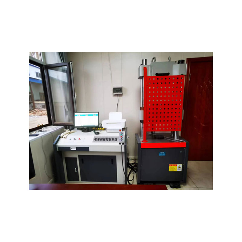
The main unit of the WAW-300B microcomputer-controlled electro-hydraulic servo universal testing machine adopts a lower-mounted cylinder structure, which is mainly used for tension, compression and bending tests of metals and non-metals. It is applicable to fields such as metallurgy, construction, light industry, aviation, aerospace, materials, colleges and universities, and scientific research institutions. The test operation and data processing meet the requirements of GB228-2021 Metallic Materials - Tensile Testing at Ambient Temperature.
Technical Parameter
1、Main Machine
The main machine adopts a host machine with a lower-mounted oil cylinder. The stretching space is located above the main machine, and the compression and bending test spaces are located between the lower crossbeam and the workbench of the main machine. The whole machine is shown in Figure 1:

Figure 1 Schematic diagram of appearance (subject to the actual product)
2、Transmission System
The lifting of the lower crossbeam is driven by a motor through a reducer, a chain transmission mechanism, and a lead screw pair to realize the adjustment of the stretching and compression spaces.
3、Hydraulic System
The hydraulic oil in the oil tank is driven by a motor to enter the oil circuit through a high-pressure pump, then flows through a check valve, a high-pressure oil filter, a differential pressure valve group, and a servo valve, and finally enters the oil cylinder. The computer sends control signals to the servo valve to control the opening and direction of the servo valve, thereby controlling the flow rate into the oil cylinder and realizing the control of constant test force, constant displacement, etc.
4、Control System
4.1 Function Introduction
lSupports tension, compression, shear, bending and other tests;
lSupports opening and editing tests, standards and steps, and supports exporting and importing tests, standards and steps;
lSupports custom test parameters;
lAdopts an open EXCEL report form, supporting users to customize report formats;
lFlexible and convenient query and printing of test results, supporting printing of multiple samples and custom sorting of printed items;
lThe program has a powerful test analysis function;
lThe program supports hierarchical management of user permissions at two levels (administrator and tester);
4.2 Software Description
lThe main interface integrates multiple functions. The main interface of the program includes: system menu area, toolbar area, indicated value display panel, speed display panel, test parameter area, test process area, multi-graph curve area, result processing area, and test information area.

Figure 1 Main interface of software test
Curve drawing: The software system provides a variety of test curve displays, such as force-displacement curve, force-deformation curve, stress-displacement curve, stress-deformation curve, force-time curve, and deformation-time curve.


Figure 2: Test process display area Figure 3: Multi-graph curve display area
Test information input interface

Figure 4 Test parameter input interface
Test steps

Test record query

Figure 6: Record query

Figure 7 Test analysis interface
Test report interface: The software operating system provides powerful report processing functions, allowing customers to print test reports according to their own needs. Test data can be stored, printed, and re-analyzed.

Figure 8: Test report
5、Safety Protection Devices
a) When the test force exceeds 3% of the maximum test force, overload protection will be activated, and the oil pump motor will stop.
b) When the piston rises to the upper limit position, stroke protection will be activated, and the oil pump motor will stop.
6、Accessories
The complete set of accessories includes: tensile accessories, compression accessories, and bending accessories.
7、Others
The instruction manual, certificate of conformity, packing list, etc., can be found in the accompanying technical documents.
Main Performance and Technical Indicators
3.1 Maximum test force: 300 kN
3.2 Test force measurement range: 2% - 100% FS (kN)
3.3 Relative error of test force indication: ≤ ±1% of indication
3.4 Test force resolution: 0.01 kN
3.5 Displacement measurement resolution: 0.01 mm
3.6 Deformation measurement accuracy: 0.01 mm
3.7 Maximum tensile test space: 550 mm
3.8 Maximum compression space: 550 mm
3.9 Piston stroke: 150 mm
3.10 Clamping diameter of round specimen jaws: Φ6 - Φ26 mm
3.11 Clamping thickness of flat specimen jaws: 0 - 15 mm
3.12 Maximum clamping width of flat specimens: 80 mm
3.13 Pressure plate size: φ160 mm
3.14 Maximum distance between two points in bending test: 300 mm (optional)
3.15 Width of bending support roller: 140 mm
3.16 Diameter of bending support roller: Φ30 mm
3.17 Maximum moving speed of piston: 50 mm/min
3.18 Clamping method: Hydraulic clamping
3.19 Overall dimensions of main machine: 770 × 500 × 1980 mm
3.20 Overall dimensions of force measuring cabinet: 1110 × 650 × 870 mm
System Configuration List
4.1 Testing machine main unit: Lower-mounted cylinder main unit, 1 set
4.2 Pressure sensor: 1 piece
4.3 Servo control oil source: 1 set
4.4 Electro-hydraulic servo valve: Digital servo valve, 1 piece
4.5 Servo control system: 1 set
4.6 Electrical control system: 1 set
4.7 Extensometer (Model: YYU-10/50): 1 piece
4.8 Photoelectric encoder: 1 piece
4.9 Computer: Brand computer, 1 set
4.10 Printer: 1 set
4.11 Standard accessories:
Tensile jaws for round specimens (mm): Φ6-Φ13, Φ13-Φ26, 1 set each
Tensile jaws for flat specimens (mm): 0-15, 1 set
Compression accessories (mm): Φ160, 1 set
Confidentiality of Technical Information and Data
5.1 This technical proposal is part of our company's technical materials. The user shall assume the obligation of confidentiality for the technical information and materials provided by us. This clause shall remain valid for a long time regardless of whether this proposal is adopted.
5.2 We shall also assume the obligation of confidentiality for the technical information and materials provided by the user.
Shandong Laishi Automation Technology Co., Ltd. (hereinafter referred to as "Laishi") is composed of a technical team with more than 10 years of research and development and manufacturing experience. The registered capital of the company is 3 million yuan. We specialize in the research and development, production, and sales of various desktop hardness testers and metallographic sampling equipment, and provide professional research and sales services for physical and chemical testing instruments, laboratory equipment, analytical equipment, and automation equipment.
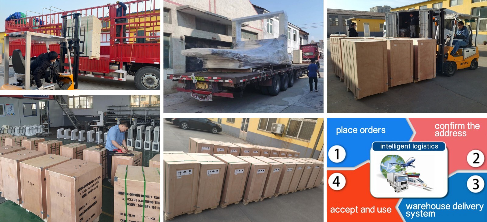
Packaging and Shipping
Have an inquiry or some feedbak for us? Fill out the form below to contact our team.
Related Product Recommendations
 WDW-100 Microcomputer-Controlled Electronic Universal Testing MachineMore Details +
 WDW-50E Microcomputer-Controlled Electronic Universal Testing MachineMore Details +
 WAW-1000D Microcomputer-controlled Electro-hydraulic Servo Hydraulic Universal Testing MachineMore Details +
") WAW-600D Microcomputer-Controlled Electro-Hydraulic Servo Universal Testing Machine (With four columns)More Details +
WAW-600D Microcomputer-Controlled Electro-Hydraulic Servo Universal Testing Machine (With four columns)More Details + Microcomputer-ControlledElectro-Hydraulic Servo Universal Testing MachineWAW-300D Technical ProposalMore Details +
 Microcomputer-Controlled Electro-Hydraulic Servo Universal Testing Machine WAW-300B Technical ProposalMore Details +
 Impact Specimen Notch Hydraulic Broaching Machine LY71-UVMore Details +
 JB-300B Pendulum-type Impact Test MachineMore Details +
 DWC-60 Impact Test Cryogenic TankMore Details +
 CST-50 Impact Specimen Notch ProjectorMore Details +
 JB- -W300A Microcomputer Control Pendulum Type Impact Test MachineMore Details +
 JB-W300DZ Microcomputer Control Low-temperature Automatic Shock Test MachineMore Details +


")


Search Starts Here
Our Email